SAW
HWEI YING
COMPUTER APPLICATIONS
PROJECT 1: MODELLING OF AN ARCHITECTURAL DESIGN

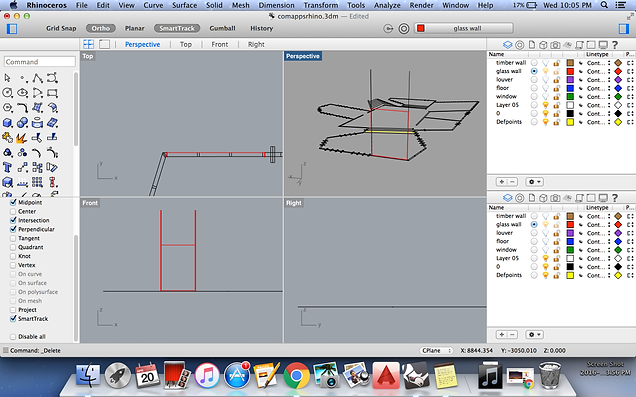
Firstly, I had imported the scanned file of my Studio 2 project to Autocad. By using commands line, offset, trim and extend, I drew the plan in Autocad. Then I imported the file to Rhinoceros.
Importing the file to Rhinoceros
File > Open > Select file
Making floor slab
After selecting all the curves in the plan, I extruded all the curves with inserting wanted thickness.
Select curve > Extrudecrv > Key in wanted thickness
Making wall
After getting the floor slab done, I had selected the curve and extruded the wall with wanted height by using command EXTRUDECRV. Hold SHIFT key to select more than 1 curve. Make sure the curves are closed so that the extruded wall is solid. Change to RENDERED to check is the extruded wall solid.
Select curves > Extrudecrv > Key in wanted height
Right click > Rendered


Extruding stairs
As the staircases are placed lower than the floor slab so when I type in (-) before typing in the desired thickness to ensure that it will extrude downwards
Select curves > ExtrudeCrv > (- desired thickness)

Making holes
To make holes on polysurface, first I used command EXTRUDE to the window frame from the plan to indicate the opening placement.
Select curves > Extrude
After protruding the window frame, I drew the outline of the opening by the command POLYLINE.
Polyline > Draw the outline of the window frame
EXTRUDE the curve of the window frame (cuboid) and use command MOVE to move it to the right position. Make sure that the cuboid penetrates the wall.
Select curve > Extrude
Select polysurface > Move

Use command BOOLEAN2OBJECTS to make the hole. Select the 2 polysurfaces that wanted to boolean, click until I get wanted result and click ENTER to confirm the opening wanted.
Boolean2Objects > Select 2 polysurfaces > Click until get wanted result > Enter

Making louvers
Use command ROTATE to change to louvers to wanted angle in the plan and EXTRUDE the louvers from the plan by entering wanted height.
Select curves > Rotate
Select curves > ExtrudeCrv


Eliminating unwanted or extra polysurface part
Create a surface with the command SURFACE FROM 3 OR 4 CORNER POINTS. Surface created must be bigger than the polysurface that wanted to be split. MOVE and place the surface between the polysurface.
Surface from 3 or 4 corners > Create a surface bigger than polysurface that wanted to be split.
Select surface > Move

Use command BOOLEANSPLIT to split the wall into 2 objects. Unwanted parts are selected and delected. Same method is used to split the extra parts of the louvers.
Booleansplit > Select polysurface
Select unneeded split surface > Delete

Eliminating the unneeded surface
Create a surface by using command SURFACE FROM 3 OR 4 CORNER POINTS. MOVE it to wanted position and use command SPLIT timber wall into 2 parts and delete the unwanted part. BOOLEANSPLIT is suitable for polysurface while split is suitable for surface.
Surface from 3 or 4 corner points > Create surface
Split > Select surfaces > Delete unneeded part


Making window frame
Use POLYLINE to draw the window frame and EXTRUDE the curve.
Polyline > Draw window frame
Select curve > ExtrudeCrv


Select the curve of window opening and use command OFFSET to create the window frame and EXTRUDE the curve. Use BOOLEAN2OBJECTS to make the window frame.
Select curve > Offset
Select curve > Extrude
Boolean2Objects > Select 2 polysurfaces > Click until get wanted result > Enter

Removing excess wall
The roof of the building is slanted so the flat wall should be cut to slanted to match the roof.
First I create a surface with SURFACE FROM 3 OR 4 CORNER POINTS and use MOVE to place it between a wall. Use command BOOLEANSPLIT to split it into 2 parts and delete the unwanted part to match thr slanted roof,
Surface from 3 or 4 corner points > Create a surface > Move
Booleansplit > Select polyframe > Delete unwanted part


Extra surface is split using SPLIT and the unneeded part is deleted.
Split > Select surface > Delete unwanted part


Making roof
To make a flat roof. POLYLINE is drawn according to the highest points of the wall. Then the curve is EXTRUDED to wanted height.
Polyline > Draw according to the wall
Select curve > Extrude


Another way to build the slanted roof.
The roof of the building is slanted and the base has different sahpes. First, I drew 2 LINES at each side and LOFT it. Besides, I alsi use SURFACE FROM 3 OR 4 CORNER POINTS to create a suface to cover the wall. Then I extrude the surfaces to desired height. Finally, I use command CAP to cover the polysurface.
Line> Loft > Create surface
Surface from 3 or 4 corner points > Create surface
Select polysurface > Cap


Creating supporting columns
Use POLYLINE to draw a square in the plan. COPY the curve and place it at wanted position. Use command EXTRUDE to extrude the columns.
Polyline > Draw square in the plan
Select curve > Copy > Place at wanted position
Select curve > Extrude

Making glass
Using POLYLINE to draw according to the window frame. EXTRUDE the curve to suitable thickness for the glass. MOVE the glass to the midpoint.
Polyline > Draw window frame
Select curve > Extrude curve
Select curve > Move to the midpoint


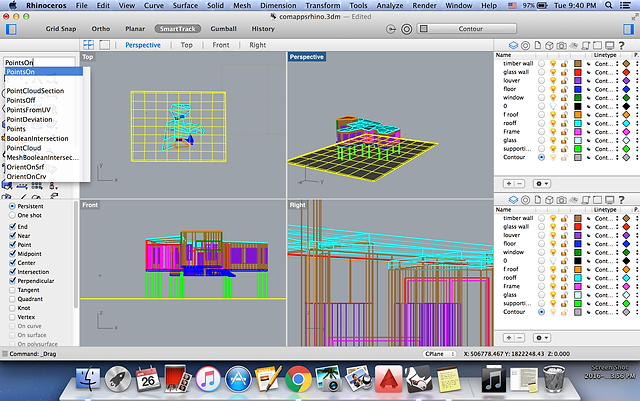
Building the contour
To build the contour, I use the command SURFACE FROM 3 OR 4 CORNER POINTS to create a surface. Next I use command PATCH to create small square spans. Then I use POINTSON to show the points and drag the points to create the contour.
Surface from 3 or 4 corner points > Create surface
Patch > Select curve > Change the surface span value to become higher
PointsOn > Move the point to wanted height


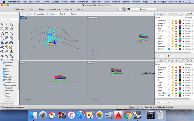
Another way to build the contour
Use POLYLINE to draw the contour line in the plan and MOVE it to desired position. Then I EXTRUDED the curve upwards to wanted height. Aftern that, I selected the surface and extrude it with command EXTRUDESRF, click DIRECTION to extrude the surface horizontally. After getting the polysurface done, use command DRAPE and create a surface on the polysurface, change the spacing value to higher value so that the contour created will be smoother.
Polyline > Draw curve
Select curve > Move
Select curve > Extrude
Select surface > ExtrudeSrf > Click direction
Drape > Change spacing value > Create surface


Rendering in Rhinoceros


PROJECT 2A: EXTERIOR RENDERINGS
STILL RENDERING WITH MATERIALS, LIGHTS, CAMERA VIEWS WITH SITE CONTEXT
Firstly, I imported all the materials layer by layer from Rhinoceros before I start to render in 3Ds max.
Max > Import > Select file > Open

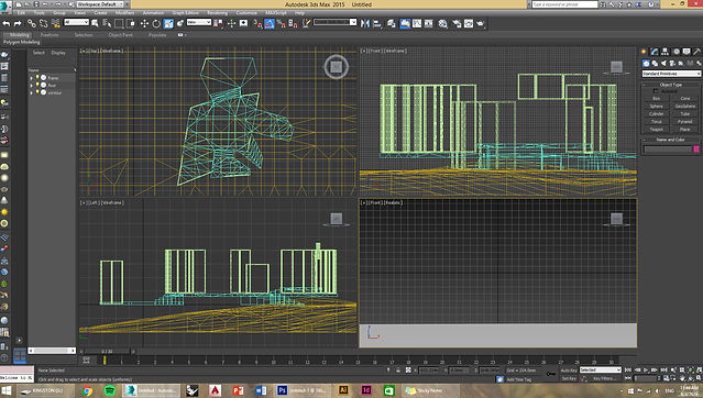
Group all the layers according to differnt materials before I get started.
Make sure that I selected Merge Object with Current Scene after I added the next layer.


Go to Render and click Render Setup. Under Common make sure that Force 2-sided is checked. Under Assigned Renderer change Production to NVIDIA mental ray before get started.
Render > Render Setup > Common > Tick Force 2-sided
Render > Render Setup> Common >Assigned Renderer > Production > NVIDIA mental ray


Use shortcut key M to open matrial editor, click Diffuse and select Bitmap, then pick the wanted material from the respective folder which downloaded from the Internet. Next back to Default again, under Map select Bump, then add Bump file to make the texture of the materials clearer.
M > Diffuse > Bitmap > Select Material from library
Map > Bump > Select file


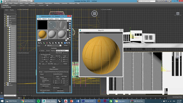
After importing all the materials, now I can start to assign the materials according to the layers. Select all the objects under respective layer, click on Assign Material to Selection. Go to Modifier, under Modifier List select UVW Map. Under UVW Map change the value of U, V and W tiles to get the wanted size of materials.
Select layer > Click on wanted material > Assign Material to Selection
UVW Map > Change value of U tiles, V tiles and W tiles


To create sunlight, go to Create, under System, select Daylight. Under Control Parameters, select Manual. Place the sun at the desired position. Use shortcut ket SHIFT + Q to test the rendering output.
Create > System > Daylight > Control Parameters > Manual > Place the sun at desired position


Add water to the landscape. In Create, draw a Plane and move it to wanted position. In Material Editor, change Standard to Arch & Design. Under Template, select Water, Reflective surface and Apply the material to the plane to create water.
Create > Plan
M > Material Editor > Arch & Design > Water, Reflective surface > Select Material > Assign Material to Selection

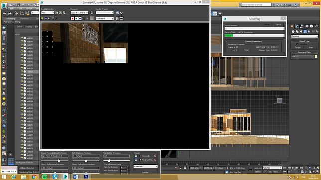
Proceed to final rendering. Firstly, go to Rendering. Under Rendering Setup, change the output size to 1000. Make sure the Image Aspect is 1.333. Under Create, select Cameras and Target. Set the camera to the wanted angle. Right click Move icon and change the value of Z to people height which is 18000.


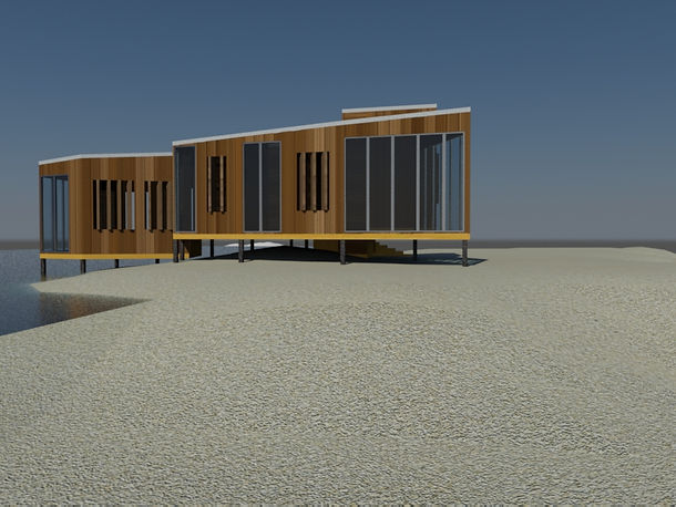


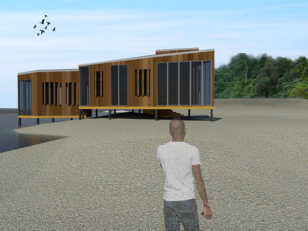
Final render view with context using photoshop.


PROJECT 2B: INTERIOR RENDERINGS
Firstly, I hide the roof up for a clearer and better view of interior. This step makes the scaling and positioning of furnitures process easier.

Next, I downloaded the furnitures from archive3d.net.

Import the downloaded furniture into 3Ds Max. Select the 3D Studio Model file type to import the downloaded furniture into 3Ds Max.


Scale the imported furniture into proper size with the help of Select and Uniform Scale.

Move the furniture with the help of Select and Move.

To change the material of the furniture. Click M to open material editor. Click Diffuse and select Bitmap and select the texture which downloaded from Internet. Select the furniture and material then click Assign Material to Selection. With the help of Show Shaded Material in Viewport to see the result.


Remember to choose Merge objects with current scene.

Rotate the furniture to desired position with the tool Select and Rotate.


Adding lighting to the lamps by using Target Light with Uniform Diffuse. Omni light isn’t working. Change to Mr Area Omni and change the Mutiplier under Intensity/Color/Attenuation in Modifier to make it brighter.

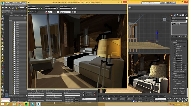

Constantly test render to check the details and result.
Use Target Camera under Create to set up the camera. Place the camera and adjust it to eye level with the tool Move. Change 1 viewpot to Camera001 to check the scene.


Go to Render Setup and change the output size to 1000 and 752. Make sure the Image Aspect is 1.33 before starting render.


Change the Image Precision (Quality/Noise) to High so produce a clearer rendering.
Final render


In this project, we are required to produce an animation video of 60 seconds to 90 seconds. Firstly, I reapply the materials as some of my files are lost.
PROJECT 3: ANIMATION
I use Nurbs Curve and Point Curve which under Create to draw the curve as the path.
Create > Nurbs Cyrve > Point Curve

Next, go to Rendering and Render Setup. Under Common and Common Parameters, activate Active the segment. Under Render Output click files to select where to save the render output and change the file type to AVI before starting to render.


Under Motion (4th icon), click position and tick it. then select path constraint.


To create a camera. Go to Animation and select Walkthrough Assistant. Then Create New Camera and click Pick Path and select the drawn curve.
Unedr Time Configuration and Frame Rate select Custom change FPS to desired frame number.

To make the water moving. Firstly, I change the Length Seg and Width Seg reading of the water (Plane) which under Parameters in Modifier to create a more detail mesh.

In Modifier, use the command Noise and change the Z reading to create the waves. Then, click on Fractal to make my wave changes more dramatically. Change the Frequency number under Animation to create a more settled wave.


To make the water move towards 1 direction which is the beach, I click on Noise and select Gizmo. Before moving the box, I turn on Autokey to activate my animation scene.Next, I drag the Gizmo along the X axis to make the wave move in that particular direction.


After I finished rendering all the wanted frames. I import all the AVI file to iMOvie to edit the video and add the sound effect.


