SAW
HWEI YING
PROJECT 2A: BUILDING MODELLING
Grid lines are created for both x and y-axis. The distance between the grid lines can be key in before creating the next grid line. The grid lines can be drawn repeated by using command CO or pressing CTRL button. Using the command DI to indicate the dimension of the grid lines.

Proceeding to elevation view to check and change the dimension of the level for each floor height.

Go to the layer “Level 1”, select Wall from the Architecture tab to draw the walls according to the created grid lines. Types and thickness of wall can be changed in the Properties tab.

Click on Edit Type to customize the thickness and type of wall whenever it is needed. Remember to Duplicate when creating a new type of wall to prevent replacing the default wall system.


Use command AL to make the wall aligned when building the wall.

Moving to Elevation to check the height of the built wall. Wall height can be changed in the Properties tab by either key in the desire height or change the Base Constraint and the Top Constraint of the particular wall.

Next, go back to layer “Level 1”. Select Floor from Architecture tab, use the Line Tool to draw the outline of the floor slab. Click on “Finish Edit Mode” after drawing the desired area.
Repeat the wall and slab building procedures for first floor and second floor.


Create stairs by using the Stair from the Architecture tab.


Select Door under Architecture tab to add doors in the project. Types and material of door can be modified under the Properties type.


Select Window under Architecture tab and select the window type in the Properties tab. After selecting the wanted type, start inserting the windows in desired places in plan view. Repeat the steps in Level 2 and Level 3for placing the doors and windows.


Select Railing under Create tab to build the railing in Level 3. Use Pick lines tools to indicate the path of the railing and click Finish Edit Mode after picking all the line.


Select Roof under Architecture tab to build flat roof. Use Rectangle tool to draw the outline of the roof. Select each roof outline and Untick the Define Slope box.


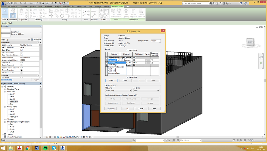
Change the wall material and finishes. Select “Edit Type” click duplicate and edit the structure of the wall to desired material and finishes.


Create slanted wall family
Go to Revit, select New and then Family. Choose Metric Generic Model Wall Based to create wall family.


Using the given template to build a new wall family. Hit the Edit Type button in the Properties tab to change the thickness of the wall. Duplicate a new wall to prevent replacement of default wall system. Change the thickness of the wall to desired thickness.


Change the dimension of the wall to the wanted height in Reference Level.


Use the command RP to create Reference Plane in Reference Level as the guideline to create void on the wall. Repeated the same step in Elevation if Reference Plane is needed in elevation view.

Use Void Blend which is under Void Forms to create the slanted opening on the wall. Use Rectangle tool to draw the bottom outline of the opening, click Edit Top and repeat the same step to draw the top opening outline. Hit the button “Finish Edit Mode” to finish the editing step.


Select Cut which is under Modify tab to cut out the window opening.
Move the created wall family to the project by selecting the Load Into Project button.

Place the created wall family onto wanted wall in the plan view. Check the result in 3D view.


Create Door Family
Go to Revit, select New and then Family. Choose Metric Door template to create door family. Click on the “Family Types” button and create a new name for the Door Family. Change the width and height to desired dimension.


Use command RP to create Reference Plane in elevation view. Command DI is applied to indicate the distance between the Reference Plane to create the door frame. Click on Label and add parameter to add the label of the specific element of the door.


Back to the Reference Level to create Reference Plane for the creation of door frame.
Select Void Extrusion under Void Forms to create the opening for placing glass panel within the door frame. Use Rectangle tool to draw the outline of the wanted opening. Check the result in 3D view.


Next, select Extrusion which is in the Create tab to produce the glass panel. Utilize Rectangle tool to create the outline of the glass panels.


Change the glass panel material to transparent glass in the Material and Finishes tab under Properties tab. New door family is done. Load the new created door family into the project.

Go to Revit, select New and then Family. Choose Metric Window template to create window family.
Create Window Family


Change the width the window in Reference Plane. Go to Elevation view to change the sill height of the window by inserting the desired distance and change the height of the window.


Create Reference Plane by command RP and indicate the measurement by using command DI. Under Label, click on Add Parameter button to create label for the elements.


Select Extrusion under Create tab to produce the frame of the window. Adjust the thickness of the window frame according to the Reference Plane created.


Select Void Extrusion to create opening for the placement of glass panel of window. Use Rectangle tool to draw the outline of the opening.


Create the glass panel by using Extrusion in Create tab. Adjust the glass panel thickness following the Reference Planes. Change the materials of glass panels to glass in the Properties tab.


Load the family to selected project.

PROJECT 2B- BUILDING DOCUMENTATION
Adding furniture into the plan using place a component and load family. As the library content is insufficient, the furnitures are downloaded from revitcity


Go to site view, under Massing & Site, use Toposurface to create the site contour. Change the elevation to desired height to create the topography. Next, click site component to add trees to the site.


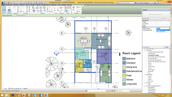
In Project Browser, Duplicate the floor plan View for room annotation. Type RM and proceed with annotating the room. Rename the room. Room Separator can be used to divide an open space with no wall to have different usage and space type.


In Architecture, under Room & Area, select Colour Schemes. In category, select Rooms. After checking the title and the colour of the room, click Apply. To visible the colour, in Properties, under Colour Scheme, change to the similar title with the title using above. In Annotate, select Colour Fill Legend to place the legend at desired place.

To create furniture plan, Duplicate the floor plans With Detailing. Under view tab, select Visibility/Graphics, unchecked Furniture under Visibility Column. In this case, all furniture will be invisible. In Filter, create new component and naming it as Furniture Layout, tick furniture to include all furniture in this stage. Change the colour of line to red and all furniture will be shown in red.


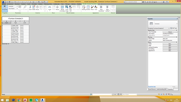
To create schedule. In View, click Schedules, select Schedule/Quantity. In the category, select furniture. Sort according to level and type. Select the required field, that is count, type and level. A furniture schedule is done. Repeat the similar steps for room schedule production.For room schedule, the required field is different, that is area, level and name .


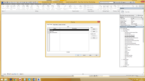
Three different phases are created for phasing, Existing, Demolish and New Construction. Firstly, go to the ground floor plan and Duplicate the view with Detailing three times and rename them as Ground Floor Plan Existing, Ground Floor Plan Demolish and Ground Floor Plan New Construction.


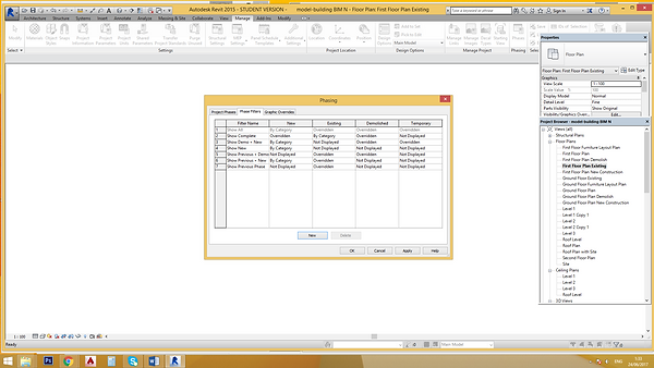
Under Manage, select Phasing. Add the three phases needed. In Phases Filter, change the setting as below. In Graphic Overrides, choose and change the wanted lines, pattern and colour. Differentiate the colour for disparate phases.


There are different Phasing Properties for each phases. Under Properties, Phasing, indicate the phase filter and phase for different phases as following:
Existing Floor Plan: All and Existing
Demolish Floor Plan: Show Complete and Demolish
New Construction Floor Plan: Show Complete and New Construction


Select all the existing and wanted component and change the Phase Created to Existing and Phase Demolished to None in Existing Floor Plan.
In the specific floor plan, pick the component that wish to be demolished, change the selected component Phase Created to Existing and Phase Demolished to Demolished. The selected will be shown in blue dotted line in Demolish Floor Plan.


In the specific ground floor, create the desired new construction by using the wall tool. Change the chosen component Phase Created to New Construction and Phase Demolished to None. The new constructed component will be illustrated in red.


Duplication with Detailing is done for 3D to create isometric view of the three phases. The Phasing Properties under Properties Bar should be changed following the Phrasing Properties mentioned above. Unnecessary components are hide to prevent blockage of the isometric view of the three phases construction.


Exploded Isometric is created by displacing the components floor by floor. 3D view is Duplicated with Detailing and Rename as Exploded Isometric. Change the view into desired angle. Select the components floor by floor and move the selected components by using Displace Elements which is under Modify. Use Path to generate paths for the exploded isometric drawing.


Interior and Exterior Perspective views are generated by placing the Camera in the floor plan. Once the camera is placed in the plan, 3D view will be generated. At this stage, the view can be adjusted to get a better viewing. Satisfied with the view, turn On the Sun and Shadow. Shadow Intensity can be adjusted through Graphic Display Option in the Properties bar. Under Lighting, adjust the shadow intensity to desired view.


Section is created by the aid of Section tool. Indicate the section line in plan, section drawings will be generated automatically. Tag Room under Architecture is used to tag the rooms shown in the section. Under View, Callout tool is used to generate two callout sections. Under Annotation, Masking Region is selected to draw footings on the produced section while Filled Region is utilized to create hatching in the drawn components. Any details can be added freely with these two useful tools.


Attached Link for Revit File and PDF A1 Sheets Viewing:
https://drive.google.com/open?id=0B2ngrXF-1DmuRU5FYzlXSzlfT1E